Project Two
Project 2: Menger Sponge
Assigned: Thursday, Sept 29, 2016
Due: Thursday, Oct 13, 2016 (by 11:59PM)
Project 2: Menger Sponge
Assigned: Thursday, Sept 29, 2016
Due: Thursday, Oct 13, 2016 (by 11:59PM)
![[Solution]](./spongesol.jpg) |
In this project, you will build an OpenGL program that shows a procedurally-generated fractal, the Menger sponge, with user interaction using mouse and keyboard camera controls. You will also be introduced to texturing by writing a simple shader that draws a checkerboard pattern on an infinite ground plane.
mkdir build
cd build
cmake ..
make
to generate an executable in the bin subdirectory. The starter code and assignment has been designed so that you can complete it modularly: the starter code contains no camera controls, but has a hard-coded camera that will allow you to see the Menger sponge, if you implement it correctly. Similarly you can implement and test the camera control portion of this assignment before adding the ground plane or modifying any shaders.
tar --exclude obj --exclude build --exclude ".*" -czf submission.tgz foldernamewhere foldername is the name of the folder containing your code. In addition to your complete source code, the .tgz file should include a README file containing, at minimum:
In particular,
Tip: After uploading your files to Canvas, it is not a bad idea to download them onto a different computer and check that it still compiles and runs, in case you accidentally leave out some important files from the .tgz. It is also wise to try to upload to Canvas well ahead of the final deadline: again, there will be no exceptions to the lateness policy, not even for technical difficulties.
Set up OpenGL context
Load geometry to render
Create Vertex Array Objects and Vertex Buffer Objects Create shader program
Compile shaders and attach to shader program
Link shader program
Create uniform (global) variables
while true do
     Clear screen
     Set up camera and light
     Tell OpenGL what shader program to use
     Tell OpenGL what to render
     Render!
     Swap buffers
end while
Each of these steps is described below in more detail.
Set up OpenGL context This boilerplate uses a helper library (glfw) to create an OpenGL context (window), request version 3.30 of the OpenGL shader language, prints some diagnostic information to the console, and performs some magic to try to make the starter code run correctly on a wider range of hardware. You can completely ignore this section for now.
Load geometry to render The geometry in this assignment consists of only two primitives: vertices, which are points in space, and triangles that connect triples of vertices. The triangles are specified using three integers, which are (zero-indexed) indices into the list of vertices. The starter code declares one vector each to store the vertices and triangles, and calls the CreateTriangle function to fill them, which creates three vertices, and a single triangle connecting them. You will be completely replacing this geometry with your own Menger sponge geometry.
Create Vertex Array Objects and Vertex Buffer Objects The geometry loaded in the previous step is stored in system RAM - in order to render the vertices and triangles, that data must be bussed to the GPU. OpenGL will handle this automatically, but you have to tell OpenGL what and where the data is. A Vertex Array Object fulfills this purpose: it's a container that contains data that needs to be shared between the CPU and GPU. The starter code creates a VAO and fills it with three arrays (Vertex Buffer Objects): one for the list of vertices, one for the list of vertex normals, and one for the list of triangles. Notice that the calls to glBufferData specify the data type and number of elements for each of these lists; you should not need to modify these lines if you add more vertices of triangles to the scene before this call. If the number of elements is later changed (for example, because the user specifies a new recursion level for the cube) the VBOs need to be updated; we do this for you automatically within the render loop.
There is another important function in this step. The GPU doesn't keep track of variables using names - all GPU variables are labeled with integers (called locations). When we write C++ code, we do give a name to the array of vertex positions (in this case obj vertices), and in the vertex shader, we will also give a name to the position variable (vertex position). Part of compiling a shader is telling OpenGL which C++ variables, and which GLSL variables, correspond to which variable numbers on the GPU. glVertexAttribPointer tells OpenGL that the VBO just created from obj vertices is vertex attribute number zero. Another such call tells OpenGL that the VBO containing vertex normals is attribute number one. Later on we will tell OpenGL that vertex attribute zero should be associated with the GSLS variable vertex_position and that vertex attribute one should be associated with GLSL variable vertex_normal. In a more complicated example, we might have more VBOs - color, for example - and these would be numbered vertex attribute two, etc.
Create shader program A shader program is a GPU program for turning geometry into pixels. A more sophisticated example might use many shader programs: one to render glass, one to render rock, another for fire, etc. In this simple example, there is only one shader program that will be used to render all of the geometry.
Compile shaders and attach to shader program As mentioned in class, each shader programs contains several shaders that play different roles in the graphics pipeline. This assignment uses three shaders: a vertex shader and two fragment shaders, which are described below. This block of code compiles all of the shaders and adds them to the shader program.
Link shader program This line finalizes the shader program; after this point the shader program can be used in the rendering loop to do rendering. As mentioned above, it is also necessary to tell OpenGL what the location numbers are of the GLSL variables; glBindAttribLocation does this for the vertex position buffer here.
Create uniform (global) variables Above we used VBOs to transfer data to the GPU. There is second way: you can specify uniform (global) variables that are sent to the GPU and can be used in any of the shaders. Like vertex attributes, these uniform variables are numbered. If we want to refer to the global variables from the C++ code, we need to look up their numbers. For example, the vertex shader declaresa light position uniform variables; perhaps it gets assigned to uniform variable number zero. The last glGetUniformLocation call looks up that number and stores it so that we can modify the variable from the C++ code later.
Clear screen We are now inside the render loop: everything above this point is run only once, and everything below is run every frame. The first thing the starter code does is clear the framebuffer; as mentioned in class, the framebuffer stores more data than just color, and this block of code clears both the color buffer (setting the whole screen to black) and depth buffer.
Set up camera and light In order to see anything, you need to specify a camera through which to view the scene, and some lights to light up the geometry. We have set up a perspective camera and a single light for you. You don't need to touch these lines: what you should take away, though, is that these lines create global matrices and vectors that are later passed to the GPU and used inside the shaders. The view matrix, which stores the camera's position in the world, is updated as the camera moves. You will be updating this code below.
Tell OpenGL what shader program to use We only have one, so there is not much choice. Later you will write a second shader program for rendering the floor.
Tell OpenGL what to render During initialization we set up some VBOs and uniform variables. Here we tell the GPU which VAO the shader program will use, then send the data in the VBOs (the vertices and faces) to the GPU. Hooking up the wrong VAOs/VBOs with the wrong shader program is a classic source of silent failure to render the right geometry.
Render! glDrawElements runs our shader program and rasterizes one frame into the framebuffer.
Swap buffers As mentioned in class, double-buffering is very commonly used to avoid flickering and tearing. This call swaps the buffers.
To complete this assignment, you do not have to understand all of the above; there are only a few steps that need to be changed to render the floor and cube. But you should familiarize yourself with how the example program is structured, as future projects will build on this skeleton.
The vertex shader is executed separately on each vertex to be rendered, and its main role is to transform vertex positions before further processing. It takes as input the vertex's position (which, as explained above, is passed in from the C++ array of vertex positions) and writes to gl_Position, a built-in variable that stores the transformed position of the vertex. This is the position that will be passed on to the rest of the rendering pipeline. Right now the shader simply converts vertex positions to clipping coordinates. It also computes the direction from the vertex to the light in camera coordinates and transforms the vertex normal to camera coordinates. These are used by the fragment shader to do shading. There is no need to transform these beyond camera coordinates (so the projection matrix isn't used on them) since the shading can be done in camera coordinates. You won't need to modify this shader in this assignment.
The fragment shader is called once per pixel during rasterization of each triangle. It diffuse-shades each triangle, so that faces that point towards the light are brighter than faces at an angle to the light. This code uses the normals previously computed and passed through the pipeline to it. You don't need to modify the cube's fragment shader in this assignment. We have provided a skeleton second fragment shader, which you will use to texture the ground plane.
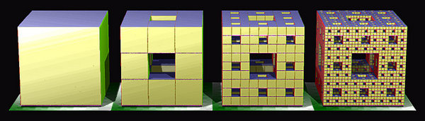 |
Your first task in this assignment is to procedurally generate the Menger sponge illustrated above. The sponge is an example of a fractal -- its geometry is self-similar across scales, so that if you zoom in on one part of the sponge, it looks the same as the whole sponge. The full sponge is thus infinitely detailed, and cannot be rendered or manufactured; however, better and better approximations of the sponge can be created using a recursive algorithm. Let L be the nesting level of the sponge; as L increases, the sponge becomes more detailed. Given L, the algorithm for building the L-level sponge is listed below.
Start with a single cube
for i = 0 to L do
     for each cube do
          Subdivide cube into 27 subcubes of one third the side length
          Delete the 7 inner subcubes (see figure, second from the left).
     end for
end for
Notice that for L = 0, the Menger sponge is simply a cube. You will write code to generate the Menger sponge for 0 ≤ L and modify the keyboard callback so that pressing any key from '1' to '4' draws the appropriate sponge on the screen. All sponges should fill a bounding box whose diametrically-opposite corners are (m,m,m) and (M,M,M), where m = -0.5 and M = 0.5.
The camera's position and orientation is encoded using a set of points and vectors in world space:
![[Camera]](camera.jpg) |
You will implement two types of cameras: an orbital camera, where center remains fixed in space as the user moves the mouse (so that the camera swivels around, or orbits, the center point), and a first-person shooter (FPS) camera, where the eye is fixed and the center moves around as the user moves the mouse. The user can toggle the type of camera by pressing 'c'. The start code already includes a keyboard callback which updates the global boolean fps_mode whenever the key is pressed.
We have provided a glm function that builds the perspective projection matrix mapping camera coordinates to screen coordinates, given values of the camera field of view, aspect ratio, and near and far clipping plane distances (reasonable defaults have been hard-coded). You do not need to modify the perspective matrix.
After rotating the camera's orthonormal frame here, and in any of the operations described below, you will need to recompute either the eye (if in orbital mode) or center (if in FPS mode) to account for the camera's new orientation.
In FPS mode, holding down the 'w' or 's' key should translate both the eye and center by ±zoom_speed times the look direction.
In FPS mode, the keys should strafe, i.e. translate the eye instead. Both operations will look the same to the user.
| Normal | Color | |
| (1,0,0) | red | |
| (0,1,0) | green | |
| (0,0,1) | blue | |
| (-1,0,0) | red | |
| (0,-1,0) | green | |
| (0,0,-1) | blue |
You should be able to represent the geometry of the infinite plane using only a small (no more than 4) number of triangles. Hint: think in homogeneous coordinates.
There are many ways of coding the checkerboard pattern; use any method you like. You may find the following GLSL functions useful: mod, clamp, floor, sin. Hint: the fragment shader, by default, does not have access to the position of pixels in world coordinates (since that information was lost earlier in the pipeline when the vertex positions are multiplied by the view and perspective matrices). You may find it useful to pass the untransformed world coordinates to the fragment shader.