Final ProjectAssigned: Thursday, November 17, 2016Proposal Due: Friday, November 25, 2016 (by 11:59 pm) Report Due: Sunday, December 11, 2016 Demo Due: Monday, December 12, 2016, 2-5pm, CLA 1.106
|
Project Description
For the final project, you get to pick a project that appeals to you. You also may work in teams of up to 3 people. It will be up to you to form teams and to choose a project. The first deliverable is your project proposal, which you should email to me and Randy on or before the proposal due date as described below. We will look at it and let you know if we think it is either too simple or too ambitious and perhaps suggest alternatives in these cases. You should tell us what you want to do, what your strategy is for accomplishing it, what your strategy is to make sure you have something to turn in even if you don't get everything working, and who will be doing which parts if you are in a team.
The project you choose should be ambitious enough to demonstrate a significant result, but not so hard that you aren't confident about shipping a reasonably complete product. Several project ideas are given below, you can choose one of these or feel free to come up with your own idea. Note that some of these projects are quite challenging, especially for one person, and others are not. If you are not sure how you would approch implmenting the project, it is probably best to choose something else. You can leaf through recent SIGGRAPH proceedings on ACM for additional inspiration.
Please note that we expect a more ambitious project from a team than we do if you're working alone.
In addition to the suggestions below, Randy has posted another list on Piazza. All of those are also reasonable projects, but note that computational geometry style projects like the last two can be subject to numerical issues even more than most graphics projects.
Some Project Ideas
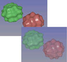
Note that some of the pictures below don't correspond to the algorithm suggested, though they all depict the idea described.
Image Processing
 |
Intelligent scissors with alpha matting. Image matting is the process of extracting a foreground element from the background so that the foreground can be placed over a novel background. Intelligent scissors is a method for interactively drawing along the contour of a foreground object while the computer tries to "snap" the curve to the nearest edge. The result of intelligent scissoring is a nice separation, but it doesn't model fractional mixing of foreground and background colors, i.e., alpha computation. In this project, you would combine intelligent scissors with alpha estimation. You could start with the intelligent scissors project from the University of Washington's 490CV course and enhance it to include a simple variant of Chuang's digital image matting method. |
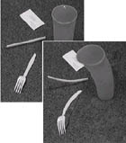 |
Object-based image editing. Allow the user to take an image, select a portion of the image, and warp that portion using a curve interface. This idea is decribed in more detail in a SIGGRAPH 2002 paper. The system in the SIGGRAPH paper has a number of components to it; we would recommend you focus on the tools for selecting a portion of an object (e.g., using an intelligent scissors algorithm) and the curve tools for deforming shapes. You can ignore the texture filling problem by working with photographs imaged against a constant background and using that color for fill. |
Rendering

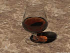
| Distribution ray tracing. Implement semi-diffuse reflections and refractions by distributing the secondary rays emanating from each surface according to a bidirectional reflectance distribution function (BRDF) of your own choosing. Allow slider control over one or more parameters of the BRDF. Stop ray recursion if the weight for a ray's color drops below a slider-selectable threshold. You can refer Ward's paper as an example of BRDF representation. You can also implement distribution ray tracing for area light sources to simulate penumbrae, for a finite aperture to simulate depth of field, and for a finite shutter interval to simulate motion blur. This extension to the ray tracing project may need to be combined with another extension such as texture and bump mapping and/or advanced material properties for teams. |

| Texture/Bump mapping. Add texture mapping to your ray-tracer
spheres, triangle meshes, and planar quadrilaterals.
Textures may be 2D or 3D (solid textures), and may be procedurally generated or optically scanned.
To map a texture onto a surface, you must compute texture indices
at each ray-surface intersection. Methods for spheres,
quadrilaterals, and triangles are described by Eric Haines in sections
2.5 and 3.3 of chapter 2 in Glassner. For a triangle mesh, you can
convert from publically available meshes
(Turbo Squid has many).
Use your texture to modulate something besides just reflectance (i.e. color). Experiment with transparency, specularity, or orientation (i.e. bump mapping). Alternatively, try modulating an interpolation between two other textures or between two entirely different shading models. See Cook's SIGGRAPH '84 paper on shade trees and Perlin's SIGGRAPH '85 paper on texture synthesis for ideas. For more information on texture synthesis (as well as a short how-to on becoming famous through computer graphics), check out Perlin's retrospective on his work. Depending on the extent of your texture-mapping extension, you may need to combine this with another extension such as distribution ray tracing and/or advanced material properties. |

| |
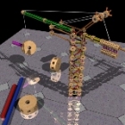
| Ray-tracing geometric primitives. Implement a class of more complicated primitives (e.g., from Hanrahan's chapter in Glassner's book). Choose wisely. Quadrics are too easy; deformed surfaces are too hard. Recommended are general swept surfaces, bicubic patches, CSG models, or fractals. Fractals are relatively easy to implement and fun to use. For extra fun, map textures onto your patches or fractals. Other primitives that can be used for terrific visual effect are particle systems (e.g., for fire and water) and L-systems (great for modeling plants). |

| Ray tracing volumes. Start by implementing spatially inhomogeneous atmospheric attenuation. Divide each ray into intervals. For each interval, interpolate between the ray's color and some constant fog color based on a procedurally computed opacity for that location in space. Experiment with opacity functions. Once you get this working, try defining a solid texture (probably procedurally) that gives color and opacity for each interval. See the SIGGRAPH '89 hypertexture paper by Perlin and Hoffert and Lewis's solid noise synthesis paper from the same year. Kajiya and Kay's teddy bear paper (also SIGGRAPH '89) may also be a good source for ideas. For smoke and clouds, you should also cast a ray to the light source to capture (one bounce of) the scattering. If you want to make your volume renderer fast, use hierarchical spatial subdivision (e.g. an octree). |
| Photon mapping. Caustics (re-focusing of light through refractive objects) and complex volumetric scatter (multiple scattering events through participating media like thick smoke and clouds) are important visual effects that cannot be modeled without tracing some rays from the light, as well as from the viewer. One method for modeling of these effects is to trace light rays and deposit photons on surfaces and in clouds -- a technique called "photon mapping." Implement photon mapping to demonstrate one or both of these effects. Henrik Wann Jensen's web page has a variety of links to examples and papers about this approach. |

| Subsurface scattering. Accurate modeling of semi-translucent materials such as skin and marble require simulation of subsurface scattering effects. Implement a distribution ray tracer that accounts for this important visual effect. Henrik Wann Jensen's subsurface scattering web page on the subject has a number of examples and pointers to papers for implementing this idea. |
| Hierarchical radiosity. This is actually not as hard as it sounds. To implement the Hanrahan hierarchical solver , the main ingredients are a simple polygonal scene, a routine to break a triangle or rectangle into a few smaller pieces, a patch to patch visibility solver (your ray tracer already does this), and a simple mechanism for traversing a hierarchy of polygons. The simplest way to visualize your results would be to write out a file in the obj format accepted by your subdivision editor extended with an rgb triple for each point in addition to the xyz values, and extend your subdivision modeler to read and render the vertex color. Alternatively, you can do a "final gather" ray-tracing pass to achieve smooth shading. For best results, combine the radiosity solution with a ray-tracing pass that incorporates specular highlights and textures. |
 |
Light field renderer. Ray tracing, especially for complex
models and many interreflections, is generally not real-time. An
alternative approach is to ray trace a set of images and then reuse these
rays when generating new images. This idea is called light field or
lumigraph rendering. Using some simple tricks with graphics hardware and
ray traced images for viewpoints on a regular grid, it is actually
possible to reuse rays in real-time to create new renderings quickly.
See Levoy and
Hanrahan's paper for details. A more complex method when geometry is
also available (in addition to the images) is described by |
 |
Non-photorealistic lighting model Technical illustration has some important characteristics which makes it very different from realistic rendering. Therefore, the popular shading model like Phong shading is not appropriate for technical illustrations. Gooch et al. introduced a shading model for technical illustrations in their SIGGRAPH '98 paper. Another option is to make a cel shader (cartoon style), or art-based rendering to make Dr. Seuss-like pictures. |
Geometric modeling

| Subdivision surfaces. Subdivision surfaces gain more and more attention from industry and have been widely used in animation production, like "Geri's Game" and "Toy Story II". As a final project, you are required to implement both non-interpolating (Loop) and interpolating (Butterfly) subdivision. Use the evaluation mask to calculate final vertex positions if necessary, and the tangent masks to calculate vertex normals. You also need to have support for feature edges and vertices. Your subdivision editor should have an interface for selecting a vertex or an edge and then marking (or unmarking) it as a feature. You can start from a previous project's subdivision surface skeleton code (in MFC only). |

| Shape deformations. Implement a system for taking a given shape, such as a triangle mesh, and deforming it based on free-form deformations or skeletal blending weights. The deformation tool should be incorporated into your animation system so that you can animate the deformation. |

| Sketch interface for modeling. Teddy is a sensational system introduced in SIGGRAPH''99 and presents a new paradigm for modeling. In Teddy, users sketch in a drawing window and the system automatically infers the underlying 3D model reasonably. As a final project, you can design your own interface for modeling or follow Teddy's design (you are not required to implement all operations introduced in the paper). You may also want to take a look at SmoothTeddy, the follow-up to Teddy. |

| Multi-resolution curves for keyframing. Create a multiresolution keyframing system which can edit the motion curves at different levels of detal. The curves should be able to interpolate the keyframe constraints by changing the coefficients at a specific level of detail. Devise a scheme which can interpolate at non-integer levels of detail. There is a paper by Finkelstein and Salesin on multiresolution curves. |
 |
Physically based vegetation. Design a dynamic model of a tree that would move realistically (e.g. for wind blowing or a person brushing through). The tree could be built using L-system rules. Different parts of the tree would have different amounts of elasticity. For a sufficiently complex tree (or lots of trees), you may need to explore efficient ways of simulating the tree physics in order to get rapid simulation. |
 |
Procedural architecture and cities. Design a general L-system
for modeling buildings (simple structure and image-based facades) and
cityscapes. Explore ways of parameterizing the buildings by attributes
such as age, style, and location. |
Animation
 | Cartoon physics simulation. Design a simulation environment that would model various aspects of cartoon physics. Augment the traditional simulation of Newtonian physics with additional constraints, damping parameters and other modifications which would produce an exaggerated cartoon-like behavior. |
 | Inverse kinematics. Implement inverse kinematics for character modeling and animation. Given a sequence of trajectories for a few end-effectors on the character's body construct the character's joint angle which would interpolate the end-effector trajectories while ensuring that the character moves "naturally". See lecture on inverse kinematics for details. There is a section on IK in the CSE558 course notes from the University of Washington. |
 | Cloth Simulator. Design a realistic cloth simulation system. Your work can focus on stable and accurate cloth simulation, handling of collisions in a reliable manner, and/or modeling of various kinds of cloth such as wool, cotton, or silk. |
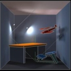
 | Rigid body simulation. Incorporate rigid body simulation with the keyframe animator. The keyframed character should be able to interact in realistic ways with the simulated objects in the scene. See this set of course notes to get you started. |
 | Efficient collision detection. Implement an efficient algorithm for determining when two rigid bodies are in contact. You can leverage ideas you developed for efficient ray tracing. |
 | Secondary motion. Develop a method for adding secondary motion to your animations so that, e.g., flesh jiggles when it moves. The technique could be built around a simple lattice that defines spatial deformation within the lattice and is driven via particle system physics. Implementing a more stable solution method, such as implicit integration, is recommended in order to have this simulation run in real-time. |
 | Motion Warping. Implement a technique for editing already existing animations, by warping the motion curves to meet the new constraints. See Zoran Popović's paper for more information. |

| Explosions. Develop a particle system approach to modeling and rendering realistic explosions (fire, dust plumes, etc.) |

| Water Flow. Simulate and render the flow of whitewater rapids. |
 |
Crowds and cars. Design a model of pedestrian crowds and/or vehicular rush-hour traffic. The crowd model should be parameterized by the number of people, demographics (age, sex, etc), and general direction. The pedestrians should exhibit some variations in behavior as well (speed, interacting with others, etc.). Lower level human movement could be built from hand-animated examples or from human captured motion data. Vehicular traffic can be parameterized by time of day, volume, source and destination. In either case, intersections between people and/or crowds must be avoided. |
Project Requirements
There are three requirements for this project: a proposal, an in-class demo, and a write-up.
Project Proposal
Email me (Don) and cc the TA with a short project proposal. Explain what you are planning to do, what you hope to learn from your project, and describe the results or artifact you intend to produce. The proposal does not need to be long, it can be as short as 3 or 4 paragraphs.
If you are working in a team, list the team members and what each person is going to work on (pair programming the whole thing is fine). It is expected that a team will pursue a more ambitious project than a single person. Each team only needs to submit 1 report.
In-class Demo
Each team will prepare a 5 minute in-class demo with 2 minutes for questions. The demo should explain your project to the class.
You should prepare in advance for the demo, since you'll be the expert, not me. If you choose a rendering project you should have precomputed some images. If you project is interactive you may not need precomputed images, but you'll want to have inputs ready that effectively demonstrate your work.
Project Report
You will email me (Don) and cc the TA with the location of a concise web page report. The report should provide:
- the necessary background to understand your project
- a description of what you accomplished
- the artifact(s) you produced
- a simple list of references
Last modified: 11/16/16 by Don Fussell fussell@cs.utexas.edu