|
Feature Based Image Morphing
Image Morphing Image morphing is the technique of seamlessly transforming one image to another. It typically involves generating a number of intermediate images which depict the transition of one image into another. Morphing is extensively used in the entertainment industry. It has been used in many movies – Terminator and Star Trek are a few examples. It is also used in the gaming industry to generate animations in video games. There are a few traditional techniques of image
morphing. A given image can be transformed into another image by
manually drawing the intermediate images and then generating an
animation of all intermediate images. Another simple technique for image
morphing is cross-dissolving. In this technique, the source image is
slowly faded out and the target image is slowly faded in. This technique
transforms the images pixel by pixel. Morphing at the pixel-level can
also be performed by defining each pixel as a particle. The particle
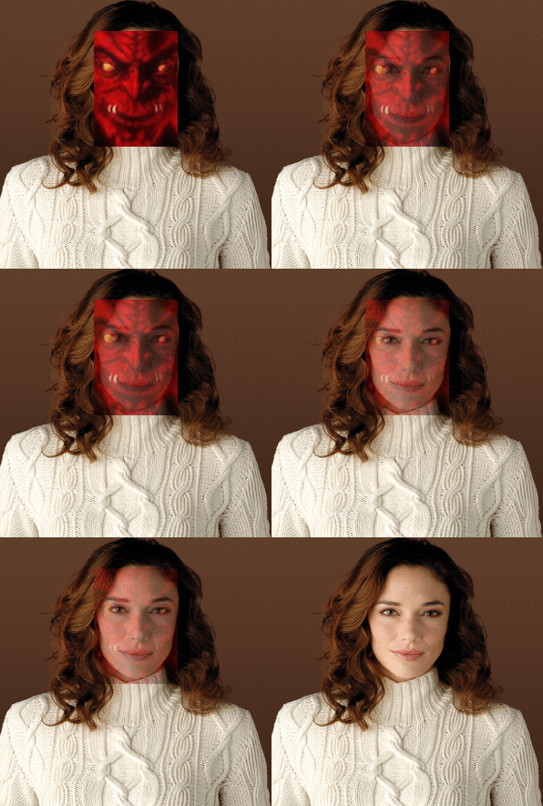
system then maps pixels from the source image to the destination image. We have implemented feature based image morphing which was introduced by Thaddeus Beier and Shawn Neely [1]. We extended this technique for applying morphs on specific regions within images of human faces. This greatly improves the quality of morphs.
Feature based image morphing consists of two steps — image warping and cross-dissolving. During image warping, the source image is transformed into the destination image by specifying an inverse transform which maps every pixel in the destination image to a pixel in the source image. This distorts the source image and this distortion can be controlled by specifying a pair of control lines. Following figure depicts how this distortion is obtained.
PQ is the control line in the destination image. For every pixel X in
the destination image, the values for u and v are obtained. Then in the corresponding control
line P’Q’ in the source image, using the values for u and v, the
corresponding pixel X’ is obtained. The color at X’ is passed to the
cross-dissolving step.
For improving the quality of warping, more that one pair of lines are
used and all color values are weighted by the following parameters — For each pixel X in
destination
Artifacts
Extension — Region morphing
During morphing faces, objects in the images which are not the parts of a face e.g. background may also get morphed. This gives unwanted results. For example, in the figure below, the user has specified proper control lines for all the features in the two faces. But because the entire images are morphed including the backgrounds, the result is unexpected and not a perfect morph.
Our system can automatically detect eyes, nose and mouth within faces and also the boundaries of the faces. Control lines are automatically drawn for each of the detected features. The detection mechanism is very simple, e.g. mouth is located approximately at one third of the height of the face from the bottom of the face. Since these are approximate locations, we also provide the user to adjust these lines to their correct positions. After clipping the faces, morphing is applied only to these regions. As shown in the figure below, this greatly improves the quality of morphing.
References
[1] “Feature-Based Image Metamorphosis”, Thaddeus Beier and Shawn Neely, ACM SIG GRAPH Computer Graphics, 1992
|


