|
Project 2: ObjectviewerAssigned: Thursday, September 27, 2018Due: Thursday, October 18, 2018 (before 11:59pm)
|
Project Description
Objectviewer is an interactive program that allows users to interact with objects defined both procedurally and via .obj files. Users will be able to create and delete instances of these objects, move the camera position, move the light source position, translate and rotate the object instances, and change the shaders used for the procedural objects, all under interactive control.To limit the amount of GUI code and ancillary work needed to implement such a program, we are providing starter code that implements much of the logic described above. There is already a menu system under mouse control for all of this functionality implemented using GLUT, a simple to use GUI toolkit for use with OpenGL. This allows you to load and delete object instances, change the shader and surface properties used for the procedural objects, and change the camera control mode.
Note that in this project, you control the camera with the mouse when you are not pushing any control keys while you move the mouse. Your assignment calls for you to add some keyboard controls for camera motion as well. If you wish to move the light source, hold down the alt key while moving the mouse, and when you have completed the assignment, holding down the ctrl key should enable rotation with the left button and spinning with the middle button, and holding down the shift key should enable spinning with the left mouse button.
Project Objectives
There are 3 parts to this assignment, each can be completed independently of the other two.
Camera Control
Implement two camera control modes.
The first of these is orbital/strafe mode. In this mode, the lookat point is at the center of the last object created, and when the left mouse button is pressed you can move the camera position laterally with side to side mouse motion, and up and down with forward and back mouse motion. The w and up arrow key should allow you to move toward the object along the view vector, the s and down arrow key away from the object along the view vector, and the a or left arrow and d or right arrow keys should move both the camera position and lookat point sideways to the left and right respectively.
The second of these is vehicle mode. When the left mouse button is pressed, mouse motion should move the lookat point sideways or up and down. w,a,s,d and arrow keys work as above, where w and up arrow are forward motion, s and down arrow are backward motion, and the other keys strafe sideways as above. In this mode you should have the feeling of driving a vehicle by pointing it in a direction and going forward or backward.
The code you will need to modify to implement these is in controller.cpp. Look for comments starting with /****** for hints.
Object Manipulation
Implement a capability to move and spin object instances that you have created. This entails implementing an object picking facility that takes inputs from the mouse and selects objects in world coordinates using this input. The essence of the picking function is the ability to create and cast a ray in world space specified by your mouse input and detect what it hits. It will be sufficient to detect whether it hits an object's bounding box.
This should be a familiar process except for the part about specifying a ray in world coordinates from mouse input. This requires that you remember that the mouse cursor is a position in screen coordinates, which is easily transformed into a position on the projection plane screen in camera coordinates. A ray can then be generated in camera coordinates from the origin through the specified point on the screen, and this can be transformed to world coordinates through the inverse of the viewing transformation. Once you have determined that a specified ray hits an object, you should make that the current object upon which transformations can be performed.
There are two transforms you should be able to specify with the mouse. First is translation. Once your picking ray intersects the chosen object, you have a t value that tells you how far away that object is from the camera origin. If you now move the mouse cursor, you can consider that moving the intersection point to a new position in space in the direction of your newly-specified ray, and the same distance from the ray origin as before. Translate the object so that the original intersection point of the object is moved to this new point.
You will specify rotations using quaternions. Start with a 0 rotation unit quaternion as the object's orientation. Then specify a new quaternion axis with the mouse as follows. Swipe the mouse in the direction of rotation. The displacement of the mouse in screen coordinates is orthogonal to the quaternion axis of this rotation. Generate the quaternion axis vector and transform it into world coordinates. Generate a rotation about this quaternion axis defined by the magnitude of the original mouse displacement and build the resulting unit quaternion.
You should have two modes for using the new quaternion. In simple rotation mode, you should concatenate the newly generated quaternion to the selected object's orientation quaternion and then perform a transformation on the object that includes the new net rotation. In animation mode, you should initiate a loop that periodically concatenates the newly created quaternion to the net orientation quaternion and performs the current transformation as long as rotation mode is enabled or until a new rotation is specified with the mouse. Animations of this type can be implemented using the idle callback in GLUT so that the transforms are performed whenever the system is not responding to other events. Use the c key on the keyboard to toggle modes.
The code you will need to modify for these capabilities is in controller.cpp, picker.cpp, and ray.cpp. Again, look for comments starting with /****** for hints.
New Shaders
You'll be modifying the GLSL shaders in the src/glsl subdirectory. In addition to the already implemented phong.vert and phong.frag shaders, you'll find ten fragment shaders with the .frag suffix and a single vertex shader named torus.vert suffix.
Task 0: Rolling up the Square into a Torus
Modify the torus.vert vertex shader implementation so that the square patch with vertex positions ranging from [0..1] in both the x and y (or u and v) components is rolled up into a torus.
Research the torus to find a parametric function F(u,v)=(x,y,z) for a torus. Hint: Wikipedia is a fine place to look.
Be sure to adjust u and v if their range is not the [0..1] range of the square patch vertex components. This figure visualizes what the vertex shader's job:

The incoming (u,v) attribute to torus.vert is named parametric.
Get the outer and inner radius of the torus from the respective x and y components of the torusInfo uniform variable. Notice that the existing code for torus.vert declares several attribute, uniform, and varying variables that are used to communicate with the C++ application and the downstream vertex shader.
When you compute your (x,y,z) position for the vertex on the torus in object space, then transform this vertex position by the current modelview-projection matrix. Hint: GLSL provides built-in variables prefixed with gl_ that track current OpenGL fixed-function state such as the modelview-projection matrix.
For subsequent tasks, you'll need to compute additional varying quantities in torus.vert for use by the downstream fragment shader. The first fragment shader is 00_red.frag that unconditionally outputs red as the fragment color so initially you can simply out gl_Position for the torus (x,y,z) position in clip space.
When you complete this task, your program should render a result like:

Task 1: Applying a Texture Decal
Once you can roll the red square into a torus, your next task is to shader the torus with a decal. This will require generating texture coordinates as a function of the parametric attributes. Output from your vertex shader to the normalMapTexCoord varying 2-component vector (s,t).
Then in the 01_decal.frag fragment shader, use this texture coordinate set to access the decal sampler.
Make sure the decal tiles 2 times in the inner (smaller) radius and 6 times in the outer (larger) radius. Assuming there are more fragments generated than vertices transformed, would this scaling be more efficiently performed in the vertex or fragment shader?
When you complete this task, your program should render a result like:
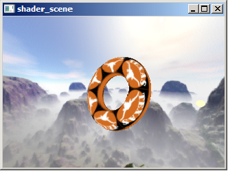
Try picking other decals from the Decal texture menu.
Task 2: Diffuse Illumination
In this task, you'll shade the torus with a per-fragment ambient + diffuse illumination term by modifying the 02_diffuse.frag GLSL shader.
To compute diffuse illumination, you'll need a surface normal vectorQ and a light vector. Both of these vectors should be normalized. (GLSL has a normalize standard library function to normalizing vectors is easy in GLSL.) The dot product of these two normalized vector (clamp to zero if negative) models the diffuse lighting contribution.
You must make sure the light and surface normal vectors are in the same coordinate system (or sometimes stated "in the same coordinate frame"). This could be object space, eye space, or surface space. For efficiency reasons (and to facilitate normal mapping, particularly environment mapping of normal mapping), it makes sense to choose surface space. In surface space, the (unperturbed) surface normal is always in the direction (0,0,1) pointing straight up in the direction of the positive Z axis.
The uniform vector lightPosition provides the position of the light in object space. The (un-normalized) light direction vector is the vector from the vertex position to the light position.
To transform an object-space direction into a surface-space, version you must construct a orthonormal basis (a rotation matrix) that can rotate directions from object space to surface space.
First compute the gradients of \(F(u,v)\) in terms of \(u\) and v, that is \(\frac{\partial F(u,v)}{\partial u}, \frac{\partial F(u,v)}{\partial v}\)
Don't trust yourself to differentiate a complicated function involved trigonometric functions? Wolfram Alpha can differentiate for you! As a simple example, try diff(u^2,u).
We call the normalized gradient of F in terms of u the tangent.
The cross product of these two normalized gradients is the (normalized) normal to the surface in object space as a function of (u,v).
In general, the cross product of the normal and tangent vector is a normalized vector mutually orthogonal to both the normal and the tangent called the binormal.
These three normalized vectors T, B, and N for the tangent, binormal, and normal respectively can be used as column vectors of a 3x3 matrix M useful for converting directions and positions to and from object and surface space. So \(\mathbf{M = [T\ B\ N]}\)
When this matrix M is multiplied by a surface-space vector, the result is an object-space vector. Because M is orthogonal, the inverse of M is the transpose of M so \(\mathbf{M^{-1}} = \begin{bmatrix}\mathbf{T} \\ \mathbf{B} \\ \mathbf{N}\end{bmatrix}\)
So multiplying \(\mathbf{M^{-1}}\) by a vector in object space is the same as pre-multiplying that vector by M to convert that vector into surface space.
In GLSL, you can construct a 3x3 matrix with the mat3 constructor with three vec3 (3-component vector) treated as column vectors.
With this approach, the vertex shader can compute the object-space light vector (simply the light position minus the surface position, with both in object space) and transform this light vector into surface space. There is no need to normalize this vector in the vertex shader, indeed, it is better to normalize it in the fragment shader after interpolation. The vertex and fragment shaders have a lightDirection varying vector intended to interpolate the surface-space light vector.
Computing the diffuse contribution in surface space is easy. The (unperturbed) surface normal is always (0,0,1) so the Z component of the interpolated and normalized lightDirection is the diffuse lighting coefficient.
(Later for some of the bumpy shaders using normal mapping, the shader will substitute a perturbed normal obtained from a normal map texture to use instead of the unperturbed (0,0,1) surface space normal.)
In the accompanying diffuse fragment shader for this task, we need to normalize the interpolated lightDirection and use the Z component as the diffuse contribution. Because the diffuse coefficient is a magnitude and should not be negative, the fragment shader should clamp the coefficient to zero with the GLSL max standard library function.
The LMa, LMd, and LMs uniform variables provide an RGB color that is the light color (hence the L) and the material color (hence the M; with a, d, and s indicating the ambient, diffuse, and specular material color) modulated on a per-component basis. See the Torus::draw method to see where these uniforms are set.
In order for the diffuse shading to reflect the light and material colors, you should modulate LMd by the diffuse coefficient and add LMa to output a final fragment color for this task.
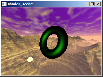
When you complete this task, your program should render a result like:

Try changing the Material and Light color settings to verify this shader is operating correctly. Move the light or spin the object. The region of the torus most facing the light surface should be brightest.
Task 3: Specular
For this task, you should modify the 04_specular.frag shader so the shading just shows a specular contribution.
Compute a Blinn specular contribution. For this you need to compute the dot product between the (unperturbed) surface normal and the normalized half-angle vector.
The half-angle vector is the average of the light vector and view vector.
Whereas Tasks 2 and 3 computed the object-space light vector and transformed it into surface space, Task 4 requires doing the same for the half-angle vector.
You have two choices:
- A: Compute the half-space vector at each vertex and interpolate this value at each vertex, or (more expensively)
- B: Interpolate the view vector and light vector and compute the half-angle vector at every fragment.
Choice B is more expensive so the shader_scene examples have a halfAngle varying to interpolate the half-angle vector, but the view vector is also available so you can choose either approach.
Use the shininess uniform to control the specular exponent.
Remember to force the specular coefficient to zero if the diffuse contribution is non-zero.
Also remember to force the specular coefficient to zero when it is negative.
Modulate the specular color result by the LMs uniform value.
Note: The initial Material has zero specular color so you should switch to a different material to see the specular highly properly. Otherwise you won't see a specular highlight if you are modulating by LMs.
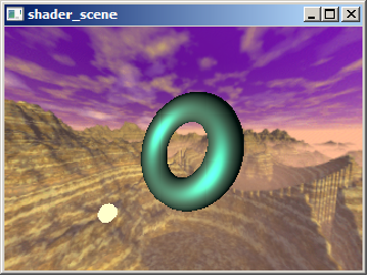
When you complete this task, your program should render a result like:
Task 4: Specular + Diffuse + Ambient
For this task, you should modify the 05_diffspec.frag shader to include the ambient, diffuse, and specular lighting contributions assuming an unperturbed normal.
When you complete this task, your program should render a result like:
With this task, the lighting should change as the Material and Light color selections change but should not depend on the Environment map, Bump texture, or Decal texture choices.
Task 5: Bumpy Diffuse
You should modify the 03_bump_diffuse.frag shader so it operates in the same manner as the shader in Task 2 except rather than using an unperturbed surface normal, a perturbed normal sampled from a normal map is used instead.
Instead of sampling the decal sampler as in Task 1, sample the normalMap sampler to fetch an RGB value that represents a perturbed surface normal, based on a height map converted to a normal map.
Normals are stored as signed components but RGB textures store [0..1] values. For this reason, the fragment shader in this task needs to expand the [0..1] RGB values to be [-1..+1] normal components.
The code for generating normals from height-field data is broken in shader_scene/texture.cpp the perturbed normal is always returned as [0,0,1]. (You'll notice a comment reading XXX fix me in this function.) You must fix the NormalMap::computeNormal method. You need to approximate the gradients for indicated (i,j) location in the height field based on adjacent height field texels to compute a surface normal. Be sure that you adjust for the fact that texels on the edge of the height field should wrap to the opposite side.
You should also use the scale parameter to scale the height field Z component. By increasing scale, the bumpiness becomes more pronounced. When the scale is zero, all bumpiness should disappear. If the scale is negative the sense of the bumpiness will reverse so outward bumps become inward bumps and vice versa. The b key increase the scale while the B key decreases the scale.
Warning: If you don't fix the NormalMap::computeNormal method, you won't get bump shading. The broken implementation always returns (0,0,1) meaning all height fields are mistakenly generated as flat normal maps.
Once the normal map texels are generated correctly and the normalMap is sampled properly in the shader, the shader needs to compute the dot product of the sampled perturbed normal and the interpolated and normalized lightDirection vector. This dot product result becomes your diffuse coefficient once clamped to zero avoid negative values.
When you complete this task, your program should render a result like:
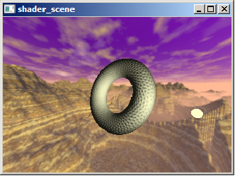
Try varying the Bump texture setting. Make sure when the normal map is Outward bumps that the bumps appear to bump outward consistently over the entire torus. Make sure the bump lighting on the torus responds to changes in Material and Light color menus.
Task 6: Bumped and Lit
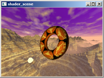
You should modify the 06_bump_lit.frag shader to include the ambient, diffuse, and specular lighting contributions with a perturbed normal from the normalMap sampler and with a decal color from the decal sampler.
Think of this task as combining Tasks 1, 3, and 4.
When you complete this task, your program should render a result like:
Task 7: Environment Reflections
You should modify the 07_reflection.frag
shader to reflect the object's surroundings based on the
Use the reflect GLSL standard library call to compute a reflection vector.
Task 8: Bumpy Environment Reflections
You should modify the 08_bump_reflection.frag shader to
reflect the object's surroundings based on the envmap environment map
and the surfaces perturbed expanded normal from the normalMap sampler.
Task 9: Everything
You should modify the 09_combo.frag shader to
combine bumpy ambient, diffuse, and specular with bumpy reflections
too. To avoid oversaturation, combine 50% of the ambient+diffuse, 50%
of the specular, and 60% of the bumpy reflection.
Your code should allow you to load objects specified by
.obj files that are contained in your objects subdirectory.
If you wish to add additional objects from the Web, just put those
files into the objects directory and when you next run the program
these should be available to be chosen. There is a phong shader
implemented for viewing these objects as an example of a working
shader. If you try to instantiate a torus only produces a red sheet.
You will need to provide a vertex shader that wraps this sheet into a
torus, and fragment shaders that shade it as selected by the gui.
Other useful resources:
All submissions should include a file named README.txt that describes
any special notes for compiling and using your program.
Parallax Mapping
Implement parallax mapping and apply it to the bump maps you've been
using above. You can also implment improvements to this technique
including steep parallax mapping and parallax occlusion mapping.
There are various tutorials on these techniques on the web, including
here
and here.
These techniques improve the realism of bump or normal mapping, at the
cost of lower performance and possibly intruducing some new artifacts.
Getting Started
For lab Linux machines: Download objViewStarter.tar.gz. This archive
contains the starting source code and a makefile. Extract the archive
and use make to build the starter code. The executable modules are
built in bin/release and bin/debug on linux and
elsewhere on other platforms, but you need to run these from the root
directory of your tar tree, where the GNUmakefile
is, or they will fail to find the files they need to startup properly.
Project Turn-in
You should turn this project in as a tar file using Canvas as usual.
Bells and Whistles
Last modified: 08/28/18
by Don Fussell
fussell@cs.utexas.edu