Vwsim
A circuit simulator for rapid, single-flux, quantum
circuits.
Introduction
VWSIM is an interactive circuit
simulator for rapid, single-flux, quantum (RSFQ) circuits. The
simulator is designed to model and simulate primitive-circuit
devices such as capacitors, inductors, Josephson Junctions,
transformers, and delay lines, and it could be extended to simulate
other circuit families, such as CMOS. Circuit models can be
provided in the native VWSIM netlist format or as SPICE-compatible
netlists, which are flattened and transformed into symbolic
equations that can be manipulated and simulated. Written in the
ACL2 logic, VWSIM provides logical guarantees about each of the
circuit models it simulates. The ACL2-based definition of the VWSIM
simulator offers a path for specifying and verifying RSFQ circuit
models. Note, our matrix solving and evaluation routines use Common
Lisp floating-point numbers, and work is ongoing to extend such
models into the ACL2 logic.
Table of Contents
Motivation
The development of our simulator began for several reasons: to
improve our understanding of the mathematics of JJ-based circuits,
to better understand what existing simulators were doing, to have a
simulator that could carry out collections of simulations, to
provide a way to alter an on-going simulation, to provide an
interactive means to control our simulation process, to provide a
programmed method for inspecting results, and to eventually provide
a formal semantics for JJ-based circuits.
We have defined the VWSIM circuit simulator with simulation
models for resistors, capacitors, inductors, transmission lines,
mutual inductance, Josephson Junctions (JJs), and VWSIM includes
voltage, current, and phase sources. VWSIM can simulate an entire
circuit model either in the voltage or phase domain. With our use
of ACL2 to implement the VWSIM electrical-circuit simulator, VWSIM
enjoys mathematical properties not available in other simulation
systems: termination, logical consistency, and a formal semantics
for reasoning about circuit models. The VWSIM system was authored
originally by Warren A. Hunt, Jr. and Vivek Ramanathan; J Moore
provided the VWSIM Gaussian-elimination solver, and Matt Kaufmann
wrote the SPICE parser and provided tremendous assistance with
subtle ACL2 issues.
VWSIM is written using ACL2 formal logic; thus the entire
simulator implementation can be thought of as a mathematical
function that animates circuit models. Given suitable input
stimulus, VWSIM can produce voltage, current, and phase records.
Developing tools using ACL2 provides a number of benefits. Each
ACL2 function, when defined, must be proven to terminate and proven
to access reachable data only; thus, all ACL2 programs are known to
terminate, without memory-reference errors.
When our effort began, we identified properties we hoped our
RSFQ circuit modeling and analysis would provide. We realized that
available simulators for RSFQ circuits were void of some properties
we desired. These shortcoming did not impede our use of
public-available simulators, but no simulator combined all of the
properties we felt were important for investigating RSFQ circuit
models thoroughly and accurately. Note, the JoSIM simulator
provides us with inspiration, and we strive to make our system as
good as JoSIM in areas where JoSIM shines while providing
capabilities not available in any available circuit simulator. We
note that our simulator is not as fast as JoSIM. Some of our goals
for VWSIM include:
- ACCURATE: We wrote VWSIM with clarity and simplicity in mind.
- RELIABLE: VWSIM is proven to terminate without memory-access errors.
- FLEXIBLE: VWSIM offers a general-purpose stimulus language.
- INTEGRAL: VWSIM supports voltage and phase-based simulation.
- TIMING: Fixed and variable time-step simulations are available.
- ACCESSIBLE: All code is freely available; runs on multiple systems.
- INTEROPERABLE: Use of VWSIM can be scripted with ACL2 or other tools.
- CAN BE PAUSED: Any simulation may be paused, saved, and later re-started.
- EXTENSIBLE: VWSIM can be extended with additional components and stimulus.
- ANNOTATION: VWSIM models can be annotated with physical parameters.
- PROMPT: VWSIM can be used interactively; signal traces are memory resident.
- FORMAL: The VWSIM is written in a mathematical modeling language.
- INTROSPECTIVE: VWSIM source code has been analyzed with the ACL2 system.
- ANALYSIS: VWSIM code and circuit models can be analyzed symbolically by ACL2.
How VWSIM Works
VWSIM accepts a hierarchical circuit description as a list of
circuit modules, which it then flattens into a list of primitive
devices with no module (subcircuit) references. The flattened
netlist is checked for consistency, making sure that there are no
undefined references or unrecognized components. With a valid, flat
netlist, VWSIM attempts to build a matrix equation that represents
a symbolic set of relations; these relations include
components (e.g., a specific resistor) and sources (e.g., some
time-varying current source), where their specific values are to be
instantiated during simulation. If the resulting matrix,
A,
is well-formed (i.e., not singular) and the sources, in
b,
are suitable, then VWSIM prepares to solve for
x in matrix
equation
Ax =
b by instantiating the symbolic
expressions in
A and
b with the current simulation
values. The solution vector,
x, represents the next-time
values for the simulation variables for a time-step value specified
by the user -- this process is repeated until simulation time is
exhausted. VWSIM records the voltages and/or phases of all
wires (nodes) as well as the currents through all components except
resistors and JJs. The currents through resistors and JJs can be
calculated after the simulation, if requested. A VWSIM user can
then process the simulation history, either by inspection, by
analysis with an ACL2 program, or by visualizing some projection of
the recorded information. See
vwsim-commands for a list of
commands that can be used to interact with the simulation.
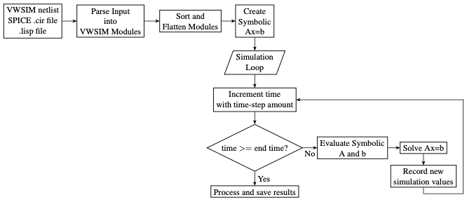
Given a textual description of a circuit, VWSIM will process and
simulate it following these steps:
- Convert input file, if in SPICE-format, into S-expressions.
- Transform S-expressions into list of circuit module references
and simulation control statements.
- Convert module references into a hierarchical netlist representation.
- Flatten and sort hierarchical netlist into a list of primitive
device references.
- Create a symbolic version of the model; i.e., create the
symbolic Ax = b matrix using the modified nodal
approach (MNA) procedure.
- Given a time step size (or using an automatically selected time
step size), solve for x in Ax = b. Use these new x values to extend
the simulation, and repeat this process until the end of simulation
time.
- Finally, process and/or save the time-value results produced by
the simulation; for instance, print results into a file of
circuit-node values or check the simulation results for specific
relationships.
Subtopics
- Vwsim-users-guide
- The VWSIM User's Guide.


