Lab 2 - Basic Router Configuration
In preparation for this lab review section 7.6 in the text and especially 7.6.1.
In this lab you will learn:
l the various configuration modes of Cisco 2621 routers
l how to set up IP addresses for such routers
l how to connect two networks with routers by setting up static routing tables
l the firewall functions of a router by setting up access lists
You need to turn in:
1. your pre-lab at the beginning of your session
2. your completed Lab 2 handout at the end of your session
Each group of 2 students will use the following equipment for this experiment.
|
2 computers with Microsoft Windows 2000 Professional |
|
1 Cisco Systems Catalyst 2900 Series Switch |
|
1 Cisco 2621 Router |
|
1 rollover cable (null modem) |
|
1 DB9m adapter |
|
3 Ethernet cables |
|
1 Ethernet crossover cable |
|
Every two groups share an additional Ethernet crossover cable |
Recap
& Introduction: In Lab #1, you learned how to
construct a TCP/IP network of four hosts via switches by assigning IP addresses
and subnet masks to the hosts. You also learned how subnetting affects a
network.
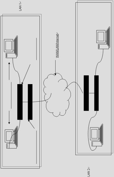
In this lab, we will be implementing the network topology in Figure 1 (on the last page of this lab) where two networks in different subnets are physically separated. There is no legend in the figure because you are required to add them in the pre-lab exercise. Our goal is to connect these two networks together. They could be on different floors in the same building. They could be in nearby buildings. Or they could be in different cities. To this end, you will first be introduced to the basics of the Cisco Internetwork Operating System (IOS). You will, then, assign IP addresses to the routers. The router acts as the gateway to its own network. Then, you will use an Ethernet crossover cable to simulate the ìcloud.î Finally, you will set up static routing tables in the gateways and test the connection.
Cisco Router Configuration ñ Introduction to Cisco Internetwork Operating System (IOS)
Cisco routers are powered by the Cisco IOS which allows the routers to be configured to perform specific tasks. Before you start configuration of a Cisco Router, you must understand the two EXEC modes available on a router: user EXEC mode and privileged EXEC mode. User mode allows you to perform basic trouble shooting tests, telnet to remote hosts, and list router system information. You know that the router is in this mode if the prompt is the router name followed by the greater than sign: RouterName>. Privileged mode, sometimes called ìenable modeî, allows for full router configuration and advanced troubleshooting. ìRouterName#î is an example of the privileged mode prompt. If you log into a router via a console or telnet connection, you enter user mode. To enter privileged mode requires that you issue the enable command. Before you actually configure a Cisco router, you must understand the two main configuration modes: global configuration mode and interface configuration mode.
Each of the routers we use has two Ethernet interfaces. Settings made in global configuration mode affect overall router operations. You can use the command configure to enter this mode after you are in the privileged mode. If you wish to configure a particular interface, you must use interface configuration mode. To enter this mode, you need to be in the global configuration mode. You then enter the interface command followed by the name and number of the interface you wish to enter. If the router is in global configuration mode, the prompt will be RouterName (config)# while in interface configuration mode it will be RouterName(config-if)#.
The BIG Picture: Task 1 is the groundwork. In task 2 and 3, group A will configure LAN A and Group B will configure LAN B. Task 4 will require the two groups work together to interconnect the two LANs.
This lab requires two groups of two to work together as a team. For each group, there will be one designated router and switch. The routers provided are Cisco 2621 models. Cisco 12.0(7) IOS is loaded on them. The switch is a Cisco 2900 model with 12 ports.
Initial Setup
- Plug one end of the rollover cable (null modem) into the console port of the router
- Locate the computer with a DB9m adapter connected to its serial port. This serial port is already configured as COM1 in Windows 2000.
- Plug the other end of the cable to the DB9m adapter.
- Verify that each of the two Pcs is physically connected to the dedicated switch with Ethernet cables.
Task 1 ñ Log on to the router using HyperTerminal
We will use a Windows program called HyperTerminal to log on to the router from one of your Pcs.
- Verify the router is turned off.
- Launch HyperTerminal at StartÆProgramsÆAccessoriesÆCommunicationÆ HyperTerminal.
You will now need to configure HyperTerminal so that it communicates with the router on COM1.
- Type router for the Connection Description Name.
- In the Connect To window the fourth field is titled ìConnect Using:î Scroll down to select COM1, and then click OK
- Confirm and change if necessary the following settings in the COM1 Properties window popped up.
|
Bits Per Second: |
9600 |
|
Data Bits: |
8 |
|
Parity: |
None |
|
Stop Bits: |
1 |
|
Flow Control: |
Xon/Xoff |
- Click OK. At the bottom left of the window, it should say ìConnectedî along with a connection timer.
- Turn on the router. Observe the boot-up procedure being displayed. This lists information about the hardware, as well as the initial configuration. We will be modifying this configuration during this lab. Be patient during this step, the router can take up to 3 minutes to boot.
- Note that there are two Ethernet interfaces at the back of the router. An IP address should already be assigned to each of these interfaces.
- Type show interfaces to see their current state.
- Record the MAC address, the speed of the interface, and the Maximum Transfer Unit (MTU) for each interface in the table below. This information is the details about each interface.
|
MAC address |
Speed |
MTU |
|
|
|
|
|
|
|
|
|
Enable |
|
|
Show |
|
|
Traceroute |
|
|
Ping |
|
- When the router boots up initially, it is in the User
EXEC mode. This has limited capabilities, which can be seen with the ì?î
command.
Type ?. Fill in the table below with the description given for the following commands.
- Observe other commands available. You will need to use this information in Task 3.
TIP: You can type the ? command at any time to receive context sensitive help.
Task 2 ñ Clear router configuration
Because we are unsure of the validity of the current configuration, we need to re-configure the router. First we need to clear the current configuration. To this end, we must be in Privileged EXEC Mode.
- Type enable to enter Privileged EXEC Mode.
- Type the password given on the chalkboard and press enter when prompt. The prompt should now end with #.
- Type erase startup-config to clear the current configuration residing on the router.
- Confirm that you wish to erase nvram filesystem and wait till it completes (up to 30 seconds).
- Type reload and confirm. This reboots the router and allows the changes to take effect.
- Type no if asked to save changes.
TIP: One of the nice things about the Cisco IOS is that it does auto complete of commands, if you type a significant part of the command and press tab, the rest of the command will be added automatically. Another feature is the ability to abbreviate commands. Yet another and most useful feature is the ability to query for command syntax. For example if you donít know what arguments are accepted for the show command, type show ? and a list of possible arguments is printed. Feel free to explore this command.
Task 3 ñ Configure an IP address to the router
Once the router has finished booting up, the previous configuration will be erased and the IOS will be in the System Configuration Dialog.
Task 3A ñ Configure FastInterface0/0 (i.e. the Routerís ìLANî interface) Using the System Configuration Dialog
- Type yes to enter.
- Type no to skip the basic management setup.
- Type yes to see the current interface summary.
- Type in the name of your group for the host name.
- Type in the password given on the chalkboard for the enable secret. This password provides access to privileged EXEC mode.
- Type in the same password for the enable password. It will tell you not to use the same password, but it is okay. Just type it in again.
- Type in the same password for the virtual terminal password.
- Type no to configuring the SNMP Network Management.
- Type yes to configure IP.
- Type no to IGRP and RIP routing, as well as bridging and configuring Async lines.
- Type yes to configure the FastEthernet0/0 interface.
- Type yes to use the RJ-45 connector.
- Type yes to full duplex mode.
- Type yes to configure IP on the interface.
- Use the following Table 1 for the next prompt.
|
|
Group A |
Group B |
Subnet Mask Address |
|
FastEtherernet0/0 |
192.168.0.1 |
192.168.50.1 |
255.255.255.0 |
|
FastEthernet0/1 |
192.168.100.1 |
192.168.100.2 |
255.255.255.0 |
Table 1
- Type no to configure the FastEthernet0/1 interface. We will do this later manually.
- Type 2 and press Enter to save the newly created configuration.
Task 3B ñ Configure FastInterface0/1 (i.e. the Routerís ìWANî interface) Manually
- Type enable to enter the Privileged mode.
- Type in the password on the chalkboard when prompt. You can tell if this succeeded by the last character of the command prompt. If it has changed to #, then you are in the Privileged mode.
- Type ?. Observe the increased number of commands available.
Write down two commands available in the Privileged EXEC mode that are not
available in the User EXEC mode.
- Type configure terminal to enter the Global Configuration mode. Note the difference in the command prompt.
- Type ? to see commands available.
- Type interface ?. Write down the names of two interfaces that
can be configured on router.
- Type interface FastEthernet0/1 to enter the Interface Configuration Mode for FastEthernet0/1.
- View the help description for the ip command.
- Type ip address XXX.XXX.XXX.XXX YYY.YYY.YYY.YYY where the Xís are the place for the IP address, while the Yís is the place for the subnet address. In this lab, the subnet address will be 255.255.255.0. Refer again to Table 1 above.
- Type no shutdown in the Interface Configuration Mode to change FastEthernet0/1 to ìadministratively upî from ìadministratively down.î
- Type CTRL-Z (or type exit twice) to go back to the Privileged mode.
- Type show ip interface brief.
- Verify that the IP addresses have been correctly assigned.
- Attach the routerís FastEthernet0/0 interface to your switch with an Ethernet cable.
- Set up the host machines with the following IP addresses and the correct gateway. Minimize the HyperTerminal Window.
|
Group A |
IP Address: |
Subnet Mask Address: |
Gateway: |
|
Computer1 |
192.168.0.2 |
255.255.255.0 |
192.168.0.1 |
|
Computer2 |
192.168.0.3 |
255.255.255.0 |
192.168.0.1 |
|
Group B |
IP Address: |
Subnet Mask Address: |
Gateway: |
|
Computer1 |
192.168.50.2 |
255.255.255.0 |
192.168.50.1 |
|
Computer2 |
192.168.50.3 |
255.255.255.0 |
192.168.50.1 |
Task 4 ñ Setting up static routing tables
This
task requires Group A and Group B to work together. If you are ahead of your
partner group, feel free to explore other commands available on router.
Now that each network has its gateway configured, we are ready to connect these
two networks together. The remainder of the router configuration will be done
across the network that you just built.
- We will use an Ethernet cable to act as the connection in the ìcloud.î Find the Ethernet crossover cable and connect it between the FastEthernet 0/1 ports on both routers.
- Click Start, choose Run, type telnet XXX.XXX.XXX.XXX where the Xís are the place for the IP address of the router interface connected to your switch. Click OK. A telnet session is now open.
- Type the password given on the board when prompt.
We will now set up a static routing table in each of the two routers. The idea is for the table to indicate that the other groupís network can be reached via the 0/1 interfaces of both routers. To create a static entry in the routing table of the router, you must be in Configuration Mode.
- Enter the Privileged EXEC Mode. (Hint: refer to Step 1 in Task 2.)
- Type config terminal.
- Wait until the other group finishes Step 6.
- Use the command ip route to set up the static routing
table.
This command requires three parameters: 1) destination network/subnet number, 2) destination network subnet mask and 3) The IP address of the next hop that can reach the destination network. As an example, Group A should issue the command: ìip route 192.168.50.0 255.255.255.0 192.168.100.2î.
Pre-lab Question 4: What command should Group B issue to set up an entry in the routing table so that machines in LAN2 can access machines in LAN1? - By pinging a host from the other group, verify that the static routing table has been created, and hosts from both groups are able to communicate with each other. Note that you need to use the command prompt to run ping.
- Type exit to return to Privileged EXEC mode.
- To view the routing table, type show ip route. List the entries in the routing table. Indicate the line of the table that represents the entry that you just placed into the table.
|
|
|
|
|
|
Gaining information about the topology of our network.
tracert, short for traceroute, responds back with information on the route that was to the destination host, for example the number of hops between the two hosts. To some degree, this information can be even used to see physical distances between two hops by looking at the time delay between the two hops.
In a command prompt, type tracert on a host within your group's network. Record the information returned. Now execute a tracert command on a host in the other group. Record this information.
Extra Tasks ñAccess Lists (Firewall Packet Filtering)
I. Introduction: The Access list is one of the most important control mechanisms to control access to both the internal and external network. Access lists consist of permit or deny statements that filter traffic based on the source address/port, destination address/port, and protocol type of the packet. In this lab, you have a chance to set up a Cisco router access list from scratch.
Access-list format
access-list [list #] [permit | deny] [source address] [source wildcard mask]
[source port] [destination address] [destination wildcard] [destination port]
[precedence precedence#] [tos tos] [log] [established]
where
[list #] : Standard IP access-lists are represented by a number in range 1-99
[permit | deny]: Either allow or deny access to certain source
[source address]: The IP address of the source
[source wildcard mask]: A wildcard mask, or inverse mask, applied to determine
which bits of the source are significant..
Unlike subnet masks, 0ís are placed in bit positions deemed significant, and 1ís are placed in positions that are not significant.
Wildcard mask examples.
|
172.22.5.2 |
0.0.0.0 |
All bit positions must match exactly. Access list will be applied only to the host 172.22.5.2 |
|
172.22.5.0 |
0.0.0.255 |
Bit positions in the first three octets must match exactly, but the last octet can be any valid number. The access list will apply to all hosts in the 172.22.5.0 subnet. |
One of the most common problems with access list is the lack of planning. Since an access list is searched from top to bottom, the configuration and order of each entry must be precise to work correctly.
Ex: The following access list is not correctly configured.
Access-list 1 deny any
Access-list 1 permit 168.243.32.0 0.0.0.255
Access-list 1 permit any
According to the access-list above, none of the computers on the network will be able to get access to the router. This is because when a condition is satisfied by a rule in access-list, router will NOT continue to check any of remaining rules.
Task 1 ñ Reset Access List
1. Make sure you are in privileged mode.
2. Type configure terminal.
3. Verify that the router is able to communicate with both computers by using the ping command with the IP address of a machine in your group and one in the other group.
Task 2 ñ Create new Access List
Here you are going to configure the router so that one of the machines from the other
group can talk with you, while the other cannot.
1. Verify that there are no access lists using show access-lists
2. access-list 1 deny 192.168.50.3 (GroupB use 192.168.0.2)
3. access-list 1 permit 192.168.50.2 (GroupB use 192.168.0.3)
Task 3 ñ Applying Access List to Interfaces
1. Enter the interface configuration mode to configure the 0/0 interface. Type
2. interface FastEthernet 0/0
3. Apply the above list (list 1) to the out side of the interface: ip access-group 1 out
4. Verify that the list has been entered, this time use the command show run.
5. And verify that the router correctly filters packets. Use ping from both hosts to verify.
6. Fill out the following table with the results of your verification.
|
|
|
Pinged |
|||
|
|
Success (Yes/No) |
192.168.0.2 |
192.168.0.3 |
192.168.50.2 |
192.168.50.3 |
|
Pinging |
192.168.0.2 |
|
|
|
|
|
192.168.0.3 |
|
|
|
|
|
|
192.168.50.2 |
|
|
|
|
|
|
192.168.50.3 |
|
|
|
|
|
Figure 1