   distance:  mm
   angle:     degrees
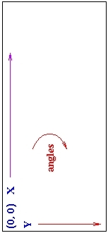
The positive X-axis of the robot extends in whatever direction the robot is facing. Assume this is North. The positive Y-axis of Flat extends East. (In a standard mathematical coordinate system the positive Y-axis would extend West).
This means that angles increase in a clockwise direction, contrary to rotation in a standard Cartesian coordinate frame. So rotating the robot through a positive angle rotates it clockwise.
For simulated Spot sonars, the sonar-ring radius is 140mm. There are 12 sonars, and sonar 0 faces straight ahead. The sonar numbers increment clockwise (following the Robot coordinate system).
For a one-laser Spot, the laser is mounted on top of the robot (at (0, 0) in Spot-coordinates). It faces forward (0 degrees) and scans a 180-degree interval, from -90 <= theta < 90.
For a two-laser Spot, the lasers are mounted on the sides of the robot at (0, -140mm) and (0, 140mm) for the left and right ones respectively. The lasers are tilted -45 and 45 degrees respectively, again in the Spot coordinate system. (The tilt is outward). Each laser scans 180 degrees, so the sensor readings overlap in front of the robot.
These values would then have to be converted to the coordinate system of the display window, which typically follows the coordinate system used in the Flat Environment. Usually this involves subtracting the y coordinate from the height of the window.
The process for converting sensor readings to such a display is described below.
   (225 >= theta >  45)     left sensor
   (135 >= theta > -45)     right sensor
Transforming this to a robot-centric coordinate proceeds as follows:
  Given:
         r      Sensor reading
         theta  Angle of the sensor reading relative
                to the robot.
         Xs     X location of sensor on the robot
                in the map coordinate system.
	 Ys     Y location of sensor on the robot
                in the map coordinate system.

     The robot-centric coordinates (x, y) are
     calculated as follows, for the angle ranges
     listed above:

       (x, y) <- (Xs, Ys) + polar->rect(r, theta)     (1)


  (1)  x' = r * cos(theta),  y' = r * sin(theta)
  Given:
         r      Sensor reading
         theta  Angle of the sensor reading relative
                to the environment (which depends on the
		orientation of the robot and the sensor angle)
         Xs     X location of sensor in the environment
	 Ys     Y location of sensor in the environment
	 Xr     X location of the robot in the environment
	 Yr     Y location of the robot in the environment
	 Or     Orientation of the robot (angle relative to the
	        environment)

     The robot-centric coordinates (x, y) are
     calculated as follows:

       (x, y) <- (Xs, Ys) + polar->rect(r, theta)     (1)

     The point is now in environment coordinates.

       (x, y) <- (x, y) + (-Xr, -Yr)        -- relative to robot location
       (x, y) <- rotate((x, y), Or - 360.0) -- undo robot rotation   (2)
       (x, y) <- (-x, y)                    -- convert to normal Cartesian


     The following LISP code performs the above operations:

      (setq transformed-point (translate-point (polar-to-rect pt) `(,Xs ,Ys)))
      (setq transformed-point (translate-point transformed-point `(,(- Xr) (- Yr))))
      (setq transformed-point (rotate-point transformed-point (- Or 360.0)))
      (setq transformed-point (reflect-y transformed-point))

  (1)  x' = r * cos(theta),  y' = r * sin(theta)
  (2)  x' = (x * cos(theta) - y * sin(theta))
       y' = (x * sin(theta) + y * cos(theta))