|
|
UPDATE: Information on our latest approach to multi-domain meshing is available here.
Description
MDM(Multiple Domain Meshing) generates unstructured tetrahedral and hexahedral meshes for a composite domain made up of heterogeneous materials, automatically and efficiently.
- The interface between two or several different materials is identified using the notion of a material change edge.
- The minimizer point is caculated for a cell shared by more than two materials which forms a non-manifold node on the boundary.
- Meshes are generated for all the material regions simultaneously and automatically while conforming to their boundaries directly from volumetric data.
|
References
Y. Zhang, T. J.R. Hughes and C. Bajaj
An Automatic 3D Mesh Generation Method for Domains with Multiple Materials
Computer Methods in Applied Mechanics and Engineering (CMAME), 2009, 199(5-8), pp. 405-415, http://tinyurl.com/NIHMS132380, PMCID: PMC2805160. (pdf)
|
Download
- Source package of MMM is delivered on demand upon explicit request.
Please contact to Dr. Chandrajit Bajaj (bajaj@cs.utexas.edu).
|
Software Usage
- Installation:
- Requirements: C++ compiler, OpenGL, Qmake + GNU make on Linux
- Building:
- Unix: run qmake and make in Volume Library's directory.
|
Further Details
- Algorithm Descriptions through Figures
(Click images to enlarge.)
1. Problem Description:
Given a geometric domain &Omega consisting of N closed material regions, denoted as &Omega0 , &Omega1 , ..., and &OmegaN &minus 1 , it is obvious that UN &minus 1i=1 &Omegai is the complement of &Omega0 in &Omega moduls the boundary of &Omega0. Suppose Bi is the boundary of &Omegai , we have &Omegai Ç &Omegaj = Bi Ç Bj when i = j. UBi may not always be manifold, it can also be non-manifold curves or surfaces.
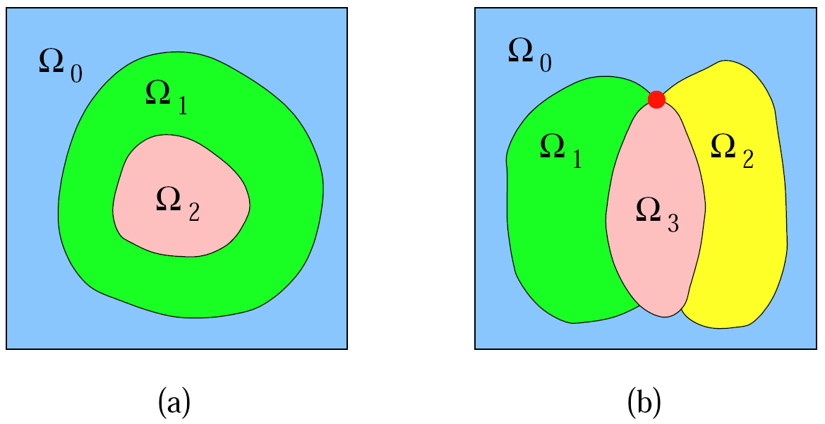
A domain with multiple materials. (a) UBi consists of manifold curves; (b) UBi consists of non-manifold curves and a square outer boundary.
2. Non-Manifold Boundary Node Calculation:

Minimizer point calculation within a boundary octree cell. The red curves are boundaries between materials, green points are intersection points of red curves with cell edges, and red points are calculated minimizers. (a) the boundary is shared by two materials, and the same minimizer is obtained when we mesh each material separately; (b) the octree cell contains three materials, and the blue point is shared by all the three materials. Three different minimizers are obtained within this cell when we mesh each material separately.
3. 2D Meshing:
- 2D Triangulation
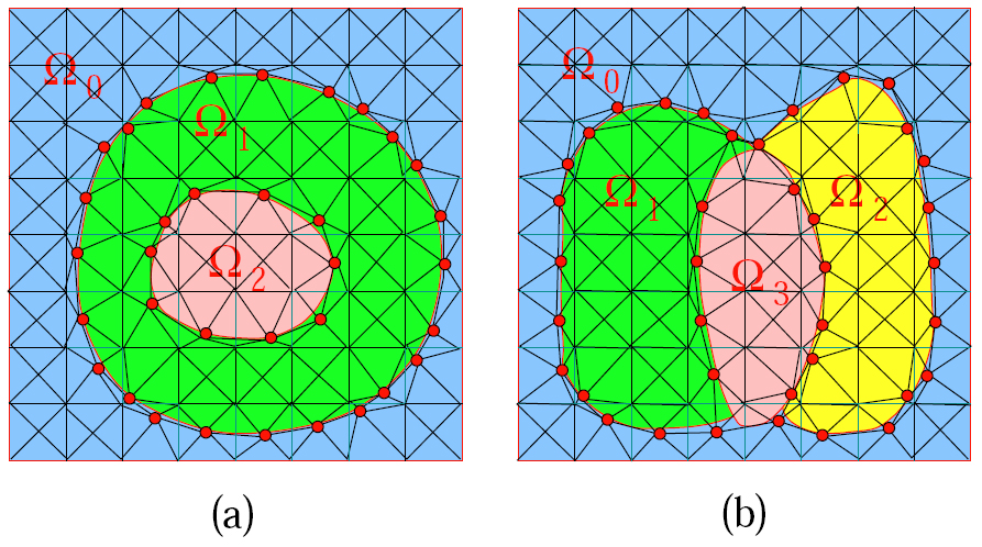
2D triangulation for a domain with multiple materials. (a) there are three materials, and UBi constructs manifold curves; (b) there are four materials, and UBi constructs non-manifold curves and a square outer boundary.
- 2D Quadrilateral Meshing

2D quadrilateral meshing for a domain with multiple materials. (a) there are three materials, and UBi constructs manifold curves; (b) there are four materials, and UBi constructs non-manifold curves and a manifold outer boundary.
4. 3D Meshing:
- Tetrahedral Meshing

Material change edges and interior edges are analyzed in 3D tetrahedralization. (a) the red edge is shared by four cells, and two pyramids are constructed; (b) the red edge is shared by three cells, and two tetrahedra are constructed. The green points are minimizer points.
- Hexahedral Meshing
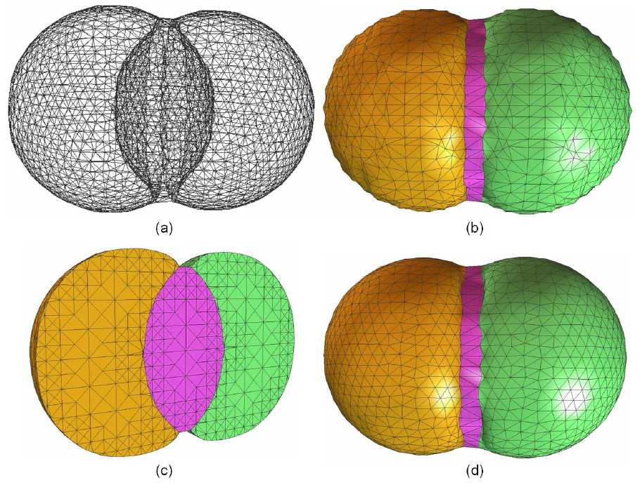
Tetrahedral mesh generation for a domain with three materials. (a) a wireframe visualization; (b) the constructed triangular surface mesh; (c) one cross-section of the constructed tetrahedral mesh; (d) the surface mesh is improved by using edge-contraction and geometric flow (100 steps with step length 0.01).
5. Mesh Adaptivity:
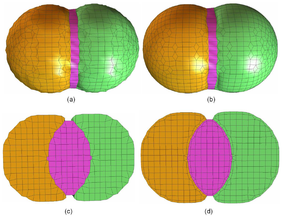
Hexahedral mesh construction for a domain with three materials. (a) surface quadrilateral mesh; (b) surface mesh after quality improvement with geometric flow (100 steps with step length 0.01); (c) one cross-section of the original hexahedral mesh; (d) one cross-section of the improved hexahedral mesh.
6. Quality Improvement:
- Tetrahedral Mesh
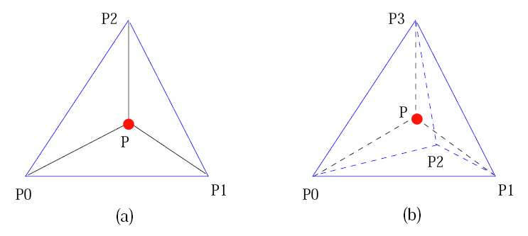
A special case for edge-contraction. In (a), a point P is embedded in a triangle P0P1P2. P and each edge of the triangle P0P1P2 construct a triangle. In (b), a point P is embedded in a tetrahedron P0P1P2P3. P and each face of the tetrahedron P0P1P2P3 construct a tetrahedron. When we contract any edge of triangle P0P1P2 or tetrahedron P0P1P2P3, duplicated and useless elements are generated.
- Hexahedral Mesh

A hexahedron [p1p2...p8] is mapped into a trilinear parametric volume in terms of &xi, &eta, and ζ. The eight basis functions in Equation (4) correspond to the eight vertices of the hexahedron.
7. Results:
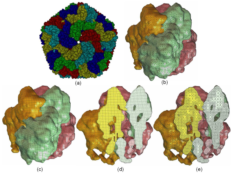
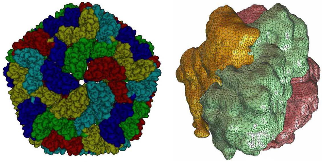
Mesh generation for the segmented rice dwarf virus (RDV) data. (a) smooth shading of the segmented RDV model [31], each color represents four 1=3 trimers; (b) a triangular mesh of one trimer consisting of three monomers; (c) a quadrilateral mesh of one trimer; (d) one cross-section of a hexahedral mesh; (e) one cross-section of a tetrahedral mesh.
|
|
|